101 classroom
Watershed/Basin
A land area that drains water to a particular water body like lakes, rivers, and oceans. Ridges, mountains, and hills usually define the boundary of a watershed/basin.
Subbasin
Subbasin is a sub-drainage land unit inside a watershed. HydroCNHS uses subbasins as the base unit for hydrological modeling. Each subbasin has a corresponding outlet. It is similar to the concept of the hydrologic response unit used in the SWAT model. However, users can freely determine the subbasins’ resolution to balance the computational cost and required resolution of the output information.
Semi-distributed hydrological model
HydroCNHS is a semi-distributed hydrological model with resolution/complexity between a lumped hydrological model and a distributed hydrological model, as shown in Fig. 1. A lumped model describes the water balance of the entire watershed as a water bucket (Fig. 1a). A distributed model simulates water responses in each grid and routes them to the downstream outlets (Fig. 1c). A semi-distributed hydrological model is a hybrid approach for the two mentioned methods. The streamflow at a downstream outlet is calculated by routing the subbasins’ (not grid) runoffs simulated by lumped models (Fig. 1b).
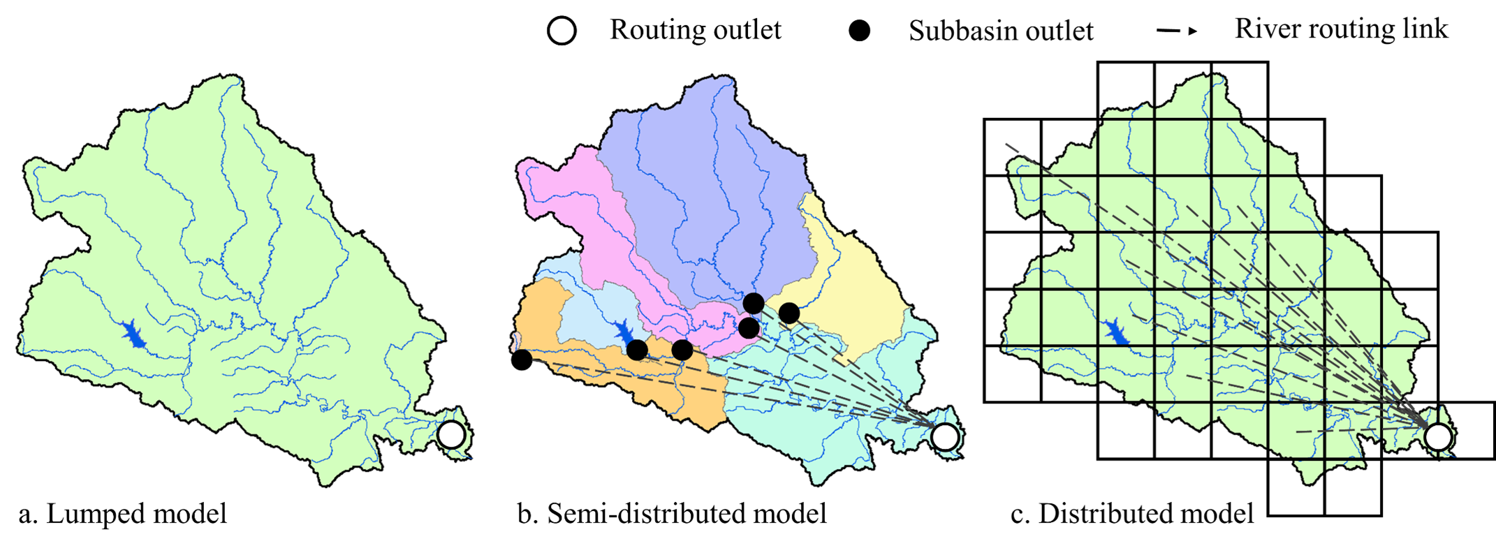
Fig. 1 Comparison of three hydrological modeling schema: a) Lumped model, b) Semi-distributed model, and c) Distributed model.
Rainfall-runoff process modeling
The rainfall-runoff process is a series of mechanisms describing how a raindrop or snowfall becomes a runoff. This process often includes evapotranspiration, interception, infiltration, snow melting, and groundwater recession. HydroCNHS supports two process-based modeling options: (1) the General Water Loading Function (GWLF; Haith et al., 1987) with nine parameters and (2) the ABCD model (Thomas, 1981) with five parameters. Detailed calculations can be found in the supplementary material in Lin et al. (2022). Users can also pre-calculate subbasins’ runoffs using their preferred rainfall-runoff models and input them into HydroCNHS.
Routing & Routing outlets
Routing captures the delay in water movement from upstream to downstream. HydroCNHS adopts the Lohmann routing model (Lohmann et al., 1998) and the unit hydrograph parameterization described in Wi et al. (2015), with the former tracing the runoff from subbasins through the river channel (i.e., inter-subbasin routing) and the latter accounting for the within-subbasin routing process (Fig. 2a). A gamma distribution is adopted to represent the unit hydrograph of within-subbasin routing.
In HydroCNHS, we define routing outlets as those subbasin outlets with routed streamflow information. In other words, for subbasin outlets that are not defined as routing outlets, HydroCNHS will not route the streamflow, and only the runoff information is stored. However, we do not encourage users to define too many routing outlets if the streamflow information is not necessary at those outlets. Minimizing the number of routing outlets will reduce the model complexity and usually lead to a better model performance.
A water system in node-link structure
HydroCNHS represents a water system in a node-link structure. Therefore, users must learn how to abstract a water system with a node-link representation and understand the routing logic behind a given node-link structure used by HydroCNHS. We introduce three typical cases, shown in Fig. 2.
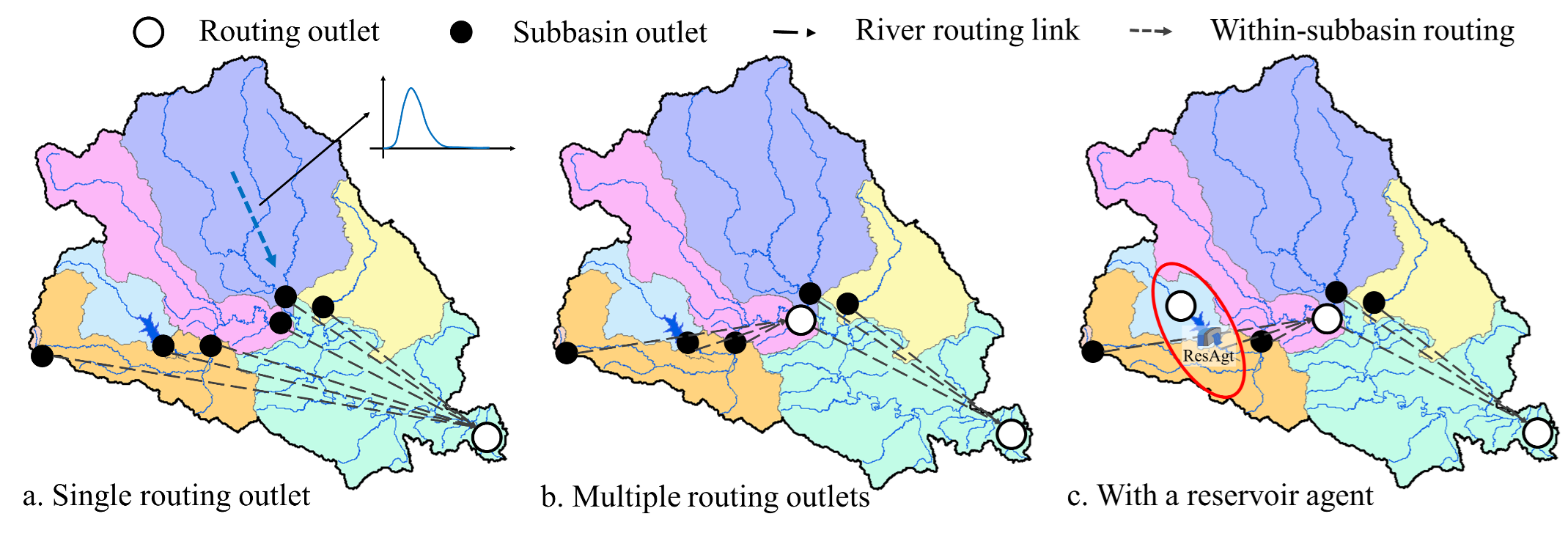
Fig. 2 Routing schema using in HydroCNHS. a) single routing outlet, b) multiple routing outlets, and c) with a reservoir agent.
Single outlet with no human components (Fig. 2a)
In Fig. 2a, we are only interested in the streamflow at the basin outlet, assigned as the only routing outlet. In this case, HydroCNHS will route each runoff generated in each subbasin to the basin outlet (white dot). Namely, each subbasin contains both within-subbasin (represented by a unit hydrologic response curve) and inter-subbasin routing.
Multiple routing outlets (Fig. 2b)
In Fig. 2b, we are interested in the streamflow at multiple (in here two) outlets. In this case, calibration is possible if streamflow data is available for the two outlets. In Figure 2b, the three most upstream outlets (black dots) are routed to the upstream routing outlet and will NOT be routed again for the downstream routing outlet. Instead, the routed streamflow at the upstream routing outlet will be further routed to the downstream outlet with only river routing (i.e., only inter-subbasin and no within-subbasin routing).
Routing with human components using Dam API (Fig. 2c)
Fig. 2c introduces human components (e.g., a reservoir; ResAgt) integrated with Dam API to the node-link structure. A reservoir is considered an in-stream object that completely redefines the downstream flow according to its water releasing rules. Therefore, such an in-stream object (e.g., a reservoir) is defined as a pseudo routing outlet used for the downstream routing. Note that the upstream node of a reservoir has to be a routing outlet to simulate the inflow. Or, we can view that ResAgt takes water from its upstream routing outlet and release water based on the reservoir’s operational rules. More details about other APIs are presented in the following section.
Design a water system with the supporting APIs
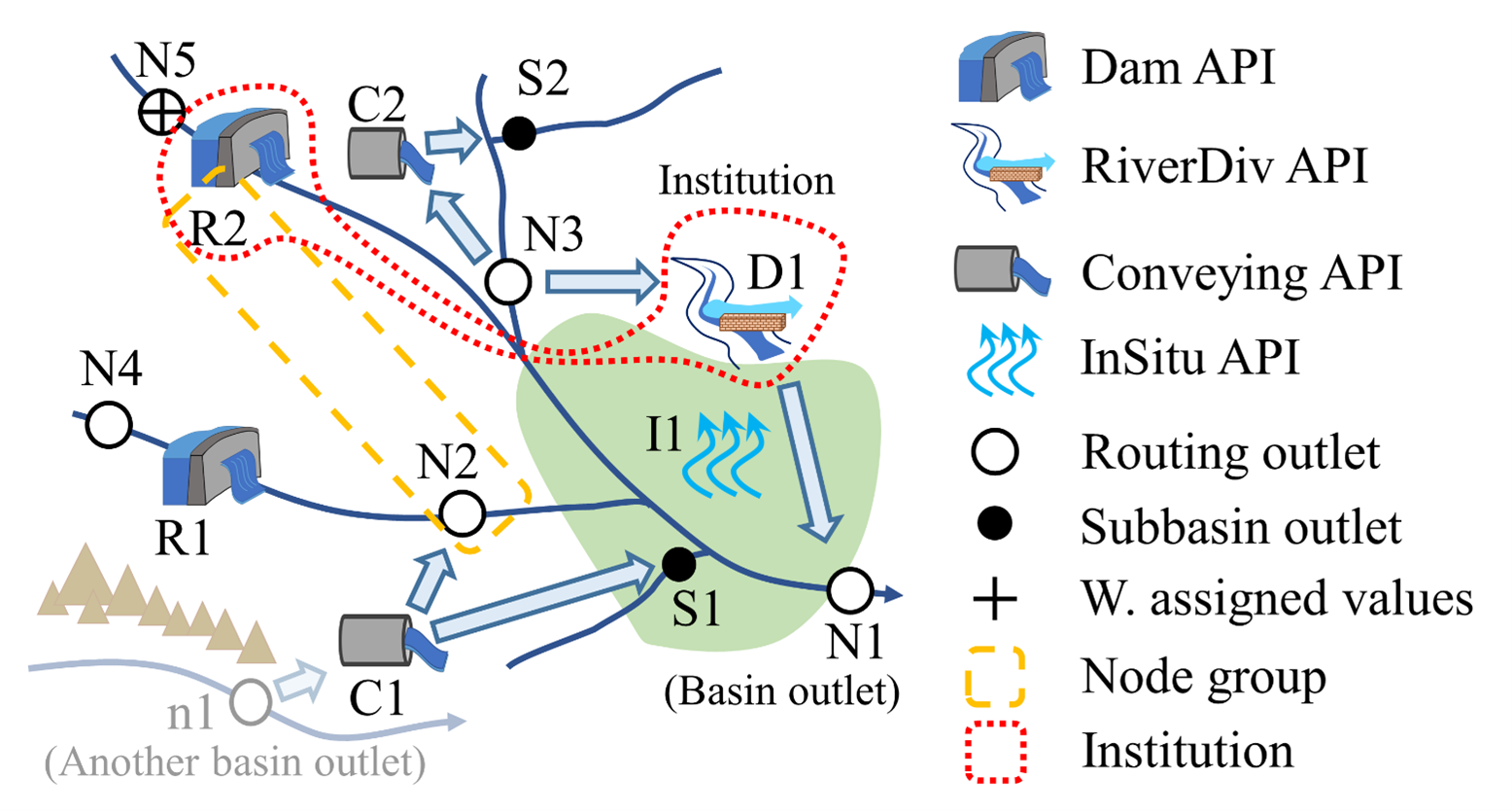
Fig. 3 A generic example of HydroCNHS coupling APIs and water system description.
The four APIs in the HydroCNHS (Fig. 3) are (1) Dam API, (2) RiverDiv API, (3) Conveying API, and (4) InSitu API.
Dam API is designed for integrating in-stream agents like reservoirs (e.g., R1 and R2 in Fig. 3) that could significantly alter the streamflow regime. Agents with Dam API will be considered pseudo routing outlets (no routing is needed) involved in the routing scheme. Namely, streamflow is directly defined by agents’ water releases decision.
RiverDiv API is created for agents that divert water from rivers and may have return flows to other outlets, e.g., diversion agent D1 diverts water from N3 and returns water to N1 in Fig. 3. This API ensures the diverted outlet is routed before agents’ diversions. At the outlet receiving return flow, the subbasin runoff and returned flow join and enter the within-subbasin routing process since return flows often have no explicit return location.
Conveying API is designed for transferring water to another outlet from a routing outlet where the routing process has already been executed. The transferred water has no within-subbasin routing (no within-subbasin delay like runoff). Therefore, they will be routed separately from the subbasin’s runoffs. If an agent wants to convey water from the downstream outlet to the upstream outlet (e.g., pump stations), the water will be delivered with delays (e.g., C2 diverts water from N3 first and delivers it to S2 at a later time step).
InSitu API is developed for agents that directly affect runoffs via “within subbasin activities” (e.g., I1 in Fig. 3). For example, those runoff changes may come from land-use changes due to urbanization or exploiting groundwater through wells. Such adjustments will be made before any routing process at each time step.
We summarize the supported connections of each API in Table 1.
APIs |
Minus (divert/take) from |
Plus (return/release) to |
||
|---|---|---|---|---|
Routing outlets |
Outlets |
Routing outlets |
Outlets |
|
Dam API* |
V |
X |
– |
– |
RiverDiv API |
V |
X |
V |
V |
Conveying API |
V |
X |
V |
V |
InSitu API** |
V |
V |
V |
V |
*Human components using Dam API will serve as a pseudo
routing outlet for the downstream routing.
**InSitu API only works on a single outlet (i.e., subbasin).
|
||||